
| The making of the palm X-Ray |
| © by Dr. Yitzhak Weissman / Advisol |
1. General
Use of stereoscopy in x-ray imaging is over 100 years old [ 1 ], but apparently it was never used routinely. There may be several reasons for that, but let us mention two that seem to be most important:
Reason 1 is fundamental, and nothing can be done to alleviate it. With all other problems concerning 3D x-ray imaging solved, the remaining question will always be: Does the extra information contained in the 3D image justify the double dose?
Radiology is shifting towards digital imaging. Digital techniques can be now used to practically solve the problem in Reason 2. The palm x-ray image was taken with a digital x-ray imager, and the raw images were digitally processed to achieve a perfect registration. Displaying the images in page-flipped CRT monitor guarantees perfect mounting. This results in a very high fidelity 3D x-ray image, which is a necessity for diagnostic purposes.
There are several principles that are common to x-ray and optical imaging techniques, but in many respects these techniques are fundamentally different. One fundamental difference is that x-ray image is made with approximately collinear (collimated) rays. Thus a simple shift of the film between the two exposures will not produce a pair of stereoscopic images.
The most common method to take a stereoscopic pair optically is to photograph the subject from two horizontally displaced positions. There is, however, an alternative method: to keep the camera in the same position, and to rotate the subject between the two exposures by a certain angle.
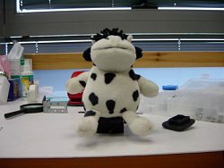
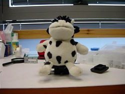
3D imaging by rotating the object is well known, and described by Ferwerda [ 2 ]. This method is attractive because it can be carried out with any standard camera. 3D images taken with this method look peculiar, because they show a 3D subject embedded in a 2D environment (see example in Fig. 1, below).
|
|
|
|
||
 |
 |
|
||
|
||||
| Figure 1: A 3D subject embedded in a 2D environment | ||||
As explained in [ 2 ], subject rotation causes keystone distortion. Ferwerda recommends rotating the subject by 1.75º between the exposures (corresponding to the 1/30 rule). At this angle, the keystone distortion is negligible. For rotation angles higher than 3º the keystone distortion becomes disturbing.
There is one very important rule that must be kept when using the rotation method: the rotation axis must be parallel to the camera film plane. Ferwerda [ 2 ] does not mention this rule.
The subject rotation method is particularly convenient for 3D x-ray imaging, and the palm x-ray image was taken this way.
The experimental setup is shown in Fig. 2. The subject was a palm phantom, and was fixed to the rotation table with tape.
Fig. 2: The experimental setup used in taking the 3D palm image
The experiment procedure was as follows:
There are four distortions in this setup that must be corrected:
• Horizontal shift
• Vertical shift
• Rotation
• Keystone
The first three are caused by the fact that the replacing cartridge is not precisely in the same location and orientation as the first cartridge. The fourth distortion is caused by the rotation of the object.
As it was planned to correct the keystone distortion, Ferwerda's limitation of 3º rotation [ 2 ] was disregarded. It was planned to display the image on a 17 monitor, so object magnification is approximately unity, and it can be displayed orthoscopically. About 40cm were assumed to be a convenient viewing distance. This corresponds to rotation angle of approximately 9º.
In order to correct the distortions, four points on the rotation table have been marked with metal pins. These metal pins can be seen in the original image, shown in Fig. 3.
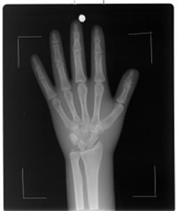
Figure 3: Original x-ray image showing the marking pins
The pins mark the corners of a rectangle, which was the reference rectangle. The distortions were corrected by applying a projective warping transformation that mapped the four corners denoted by the pins to the corners of the reference rectangle. This procedure was applied to both images in the stereoscopic pair.
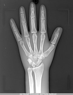
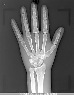
The resulting stereo image is shown in Fig. 4. In addition to the warping correction, the original images were digitally enhanced and the artificial pin marks were digitally erased.
|
|
|
|
||
 |
 |
|
||
|
||||
| Figure 4: Final Stereo Pair | ||||
All x-ray resources used in this study were provided as courtesy by Orex Computed Radiography Ltd. Special thanks are due to Dr. Varda Gottfried from Orex for technical support, encouragement and image enhancement.
The method described in this article was submitted as a provisional patent by the author, and has a patent pending status.
[ 1 ] Thomson E.: Stereoscopic Roentgen pictures. Electr Eng, 1896, 21: 256
[ 2 ] Jac G. Ferwerda, The World of 3D, a practical guide to stereo photography, 3D book productions, the Netherlands , (1990 )
[ 3 ] George Wolberg, Digital Image Warping, Wiley-IEEE Computer Society Pr; 1st edition (July 27, 1990)
 |
|
|

| Back to the Stereoscopy.com FAQ Page |