

| Lenticular Imaging |
Lenticular Imaging is not exclusively used for Stereoscopic Imaging. A number of other applications exist as well. However, each of them uses the same basic principle as described in this section of the FAQ. For completeness, we mention all applications including, of course, 3D.
What is lenticular, anyway?
The lenticular image combines two components. The first is a plastic sheet (or glass plate), incorporating a series of parallel lenses that magnify portions of a segmented image that is printed or otherwise attached to the back (second surface) of the lens sheet. The second component, a segmented image on the second surface, is composed of alternating slices of two or more original images. The slices are interlaced (combined in alternating patterns) in such a way that, when viewed from one angle, the sheet displays a visually seamless version of one of the originals, but viewed from another angle, we see a different image.
How do they do that?
The component most critical to lenticular effects, of course, is the long, thin lenticular lens or lenticule (see Fig. 1, a “blueprint” of the single lenticule.) Its curved surface (formed on the viewing side or first surface of the sheet via extrusion or casting) forms what is called a plano-convex lens. It redirects and refocuses the viewer’s line of vision onto one of two or more stripes of the printed image positioned behind each lenticule (see Fig. 2 below). |
Each lenticule operates similarly to the more familiar magnifying glass. At a certain distance, the magnifying glass will focus light to an intense, but small spot. Adjust the position of the glass up or down and the sharp focus is lost, the spot is larger but washed out (see Fig. 3). |
The lenticular effect, however, is viewed in reverse, and changes focus in only one dimension. The lenticule takes a thin, vertical slice of the total image area that it spans and magnifies it in such a away that, from the proper viewing distance and angle, the thin slice appears to fill the entire lens surface (see Fig. 4). As a result, the viewer can see only one slice per lenticule at any time, regardless of viewing angle. |
The lenticular image (printed direct to or laminated to the sheet back) is composed from multiple images that have been sliced into stripes and reordered (via computer graphics software), in a process called interlacing. The number of stripes per lenticule is predicated on the type and extent of the illusion that you are trying to create. Positioned behind each lenticule is a group of stripes, one from each original image, arranged in the reverse order that they will be viewed. (If the illusion is “motion,” for instance, and the observer’s viewing angle is expected to shift from left to right, slices are arranged in order from right to left.) |
The image changes (moves from one illusion phase to another phase) when a shift in viewing angle brings a different stripe into focus, magnified to fill the width of the lenticule. This results in what appears to be a seamless image (one phase of the illusion) across the face of the lens sheet. As viewer perspective changes, an adjacent stripe comes into focus, and the viewer sees another phase (see Fig. 5).
|
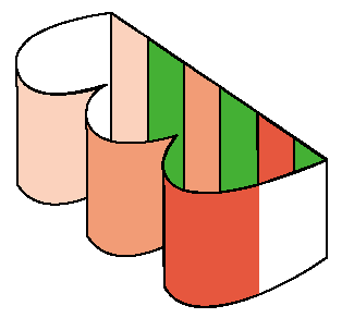 FIG. 6: In a
two-phase illusion (called a “flip”) the computer artist must
prepare art that contains slices of the two original images the are precisely
one-half the width of the period (the width of a single lens).
 |
Interlacing
Many effects (see “What do we see?” section, below) can be created, based on the type of artwork selected, the total number of original images (= the number of phases, which in turn determines the number of stripes per lenticule) needed to produce the illusion.
For example, a solid red image and a solid green image could be sliced (via computer image manipulation) and recombined as the two phases of the simplest version of the lenticular illusion aptly named the “flip.” As viewer perspective changes, it flips from one image to the other. So if the lens sheet has 15 lenticules per inch and there must be two stripes per lenticule width (called a period); assuming each period is 1/15” wide, each stripe must be .0333” wide. These stripes are then interlaced in the following pattern (see Fig. 7):

FIG. 7: Here, in
cross-section, the two-phase “flip” image slices are shown in a
repeated pattern, which must be arranged across the back of the lens sheet in
register with the periods (lens widths), and must run, length-wise, in parallel
with the lenticules.
Period 1: Red1, Green1
Period 2: Red2, Green2
Period 3, Red3, Green3
Period 4: Red4, Green4 …
to the end of the lens sheet.
Though lenticules may be arranged vertically or horizontally in small formats (horizontal arrangement is popular for hand-held images, which are easier to hand-rotate on a vertical arc) large-format images typical feature vertical arrangements, because viewers (we human bi-peds) typically walk or drive past the image from right to left or from left to right. (See Fig. 8 below).
Lenticular animation is best seen, by the way, when viewer movement is parallel to the sheet surface.) More than two images may be sliced and ordered within a period (historically, there have been lenticular images with as many as 35 stripes per period). Use of multiple images makes it possible to create progressive image change. The three-phase series of gradient images in Fig. 5 illustrates a simple progression, seen as the viewer moves past. Again, each lenticule focuses the viewer’s sight on just one of the three stripes. At any point in time or travel, the viewer sees the gradient images “flip” in succession, from red to green to blue phases. See also Fig. 9, which is an overview of the various stages of lenticular-image creation. Beginning with original images, it illustrates slicing, reordering and positioning in relationship to the lenticules. |
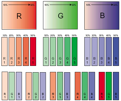
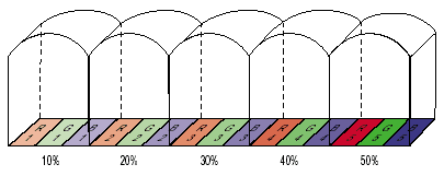
FIG. 9: The basic
steps in lenticular image preparation: Original images are selected (based on
the effect desired). With the aid of a computer graphics program, scans of the
originals are sliced, then reordered into a series. The reordered stripes are
saved as a single image and printed or imaged, either directly onto the second
surface (backside) of the lens sheet or onto a material that is subsequently
adhered to the second surface.
What do we see?
Lenticular’s strength as an
animation process is its versatility. Lenticular can create six basic illusions
or modes— flip, morph, zoom, motion, depth and 3D. Each can be created
in reflective or transmissive (backlit) format, and none requires eye glasses
or other optical devices for viewing. In addition, combinations of the six basic
illusions can be produced on a single lens sheet. The illusion we see is determined
by the method of interlacing — that is, the way that two or more pieces
of original art are sliced and reordered under each lenticule. The lens is a
key factor in the successful creation of these various effects. As indicated
below, each illusion mode poses unique imaging challenges and each performs
best with lens sheets of a particular thickness and lens frequency. In addition,
while some illusions can be created with spot colors, others require four-color
process. Here are the basic six, with a description of the imaging methods and
materials best suited for each.
Flip
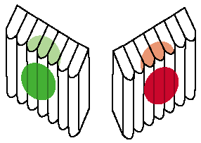
FIG. 10: A lenticular “flip, illustrated in its
simplest (two-phase) form, features one slice form each of two original images
per period (the distance across the width of a single lenticule). Visually,
the result is an instant change from one image to the other, as viewing angle
changes.
In this mode, a change in viewer
perspective causes one image to change or “flip” to another. The
ideal “flip” graphic is comprised of high-contrast images, such
as a spot color that changes on schedule to another image (see Fig. 10), with
no ghosting or cross-talk in either phase (visually speaking, you’d see
no evidence of one image when the other is in view. On the plus side, “flip”
requires a wide-angle lens sheet, thinner than lenses for “depth”
or “3D” illusions and therefore less expensive. It typically features
the fewest phases per lenticule, as well. The fact that as few as two phases
(two stripes) may be required per lenticule means that image resolution is somewhat
less demanding. In turn, this affords the printer a wider window of tolerance
for color-to-color registration. However, color-to-sheet register is very demanding.
The “flip” illusion is the most sensitive to cross talk, caused
by print-to-lens mis-register due to skew, poor alignment or improper sizing.
For instance, any rotation of the image, skewing the stripes out of parallel
to the lenticules, will easily destroy the sharp, abrupt change desirable in
a “flip.” Not surprisingly, this mode places greater demand on image
registration than any of the other illusions.
Morph
The lenticular “morph” is a more complex rendition of the simple “flip.” Here there are start and finish images, but also an in-between series of hybrid phases — images that progressively change from the initial to the altered (morphed) state (see Fig. 11). Many computer software packages, in fact, have a “morph” feature that can be used to create the in-betweens, prior to interlacing.
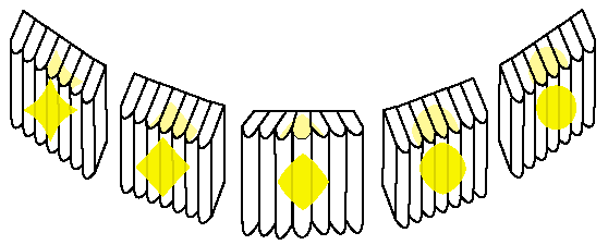
FIG. 11: The “morph”
is a progressive change, from one image to another, with in-between stages.
The illustration shows a five-stage progression, which requires five original
images and requires five image stripes within each lenticule.
The illusion works best on a thick, wide-angle lens with a low lens count. This allows the greatest number of transitional phases for single (for instance, image A to image B to image C) or dual (as in A to B to C to B to A) morphing (B indicating one or more transitional images). High-speed transitions will demand a thicker lens. Overall registration demands are high, especially for transitional elements, and contrast is of paramount importance for the start and finish images.
Zoom
More trouble in pre-press, but more forgiving on press, this technique places stripes of progressively enlarged versions of a single object — independent of the background — behind each lenticule. The change in observer viewpoint makes the featured object appear to move away from or move toward the viewer, depending upon the direction of travel. (Fig. 12). “Zoom” will do well on a longer lens sheet and a slightly out-of-focus background may add to the affect. Again, highspeed transitions will demand a thicker lens sheet.
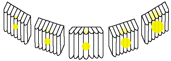
FIG. 12: The “zoom”
illusion begins with an original image and a series of progressive enlargements
of the original. In the illustration, five progressively enlarged images of
a ball have been sliced, reordered and positioned behind the lens sheet. When
the viewer moves in one direction, the ball appears to come closer. Viewed while
the observer moves in the opposite direction, the ball appears to recede.
Motion
Typically made from selected frames of a motion picture film or video segment, “motion” images feature key (rather than all) in-between frames of the motion picture (see Fig. 13), and the observer mentally “fills in” the blanks. The virtual motion is affected greatly by the speed of the change in the viewer perspective (for instance, how quickly the observer passes by in an automobile). The ideal product features high-speed, fluid transitions of the animation from one frame to the next. A slight blur or loss of contrast in the in-between phases is permissible, because it will help convince the viewer’s mind to “fill in” the animated sequence. Nevertheless, this illusion will typically have the highest number of phases per lenticule. therefore, it requires very high-resolution images. “Motion” will force the printer to a lower lens count both to accept the multitude of phases and to achieve high-speed transitions at a long viewing distance. As a result, “motion”performs better on a medium-to-long lens.
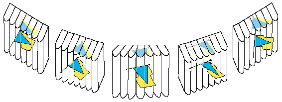
FIG. 13: Lenticular
“motion” animates the image, using a series of (typically photographic)
images, such as selected frames from a movie or video segment. It’s effectiveness
in terms of visual impact depends directly on the number of in-between images,
and can be further enhanced if the computer artist encourages the viewer to
fill-in the missing ‘steps’ through the use of blurred images, particularly
when intent is the illusion of speed.
Depth
Here, a two-dimensional image is isolated from its surroundings with silhouette masking. In the finished product, the isolated portion appears to loom in front of the lens sheet as though it had been suspended in mid air while the background recedes into the sheet (see Fig. 14). The goal is to echo layer the image so as to take advantage of human binocular vision at the proper point of convergence. Such an effect in a large format may require a 100-mil lens thickness (or larger) to create sufficient separation between background, the lens sheet and the foreground if the sheet is to be viewed from afar. Neither registration nor resolution and contrast will be as demanding for this product. The critical aspects are the art echo layering and the properties of the long lens.
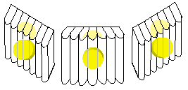
FIG. 14: “Depth”
images appears to suspend an object in mid-air, in part, through the use of
computer masking techniques, and often with the aid of a slightly out-of-focus
background. Here, the illustration simulates the effect the image has as it
takes advantage of human binocular vision, in which the same object is naturally
viewed by each eye at slightly different angles.
Virtual 3D
Similar to the properties and requirements of “depth” illusion, this image is very appealing but, in production, forgiving. However, 3D will nearly always run in four-color process, and it will therefore tend to have the largest digital file size. The art is prepared via computer as a 3D rendering with all of the visual cues that indicate a third dimension: Perspective, spatial frequency, recessive contrast and resolution, size, position, imposition, occlusion, radiosity and luminosity control are a few of the cues to three-dimensional imaging. These elements can be very subtle and if so, the computer-graphics segment of 3D image development will be more demanding than the “depth” illusion. Lenticular 3D uses positive and negative parallax and gives the viewer the “mid-air” look of “depth” but the suspended object also appears to have contours and mass (see Fig. 15.)
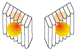
FIG. 15: In “virtual
3D” effects, various computer-aided image enhancements augment the effect
of the “depth” illusion to render what appears to be a fully threedimensional
object, as the viewer passes in front of the lens sheet. As illustrated, the
suspended circle appears to be a sphere.
Lenticular screen printing?
Historically, the lenticular imaging method of choice is lithography. Still is, for large-volume printing, prototyping, sampling, proofing and very short-run production can be done via digital inkjet, digital photography, silver contact photography and direct-to-lens photography. But screen printing is an excellent option, given the right conditions. Set up costs of litho, even with CTP, are high enough to leave a large pricing window between litho and the short-run length digital and photographic methods. Inside that window, screen-printed lenticular sheets can be price-competitive. In addition, litho is best suited for a lot of small pieces, printed on thin-gauge stock, which means close viewing distances. Finally, lithographic, photographic and digitally produced images are generally less suitable for outdoor exposure. That leaves the large-format, outdoor, longviewing-distance stuff to you.
The target market, then, for screenprinted lenticular images is the same as for most forms of print advertising — print buyers who purchase large-format (20” x 24” or greater) images in quantities too high for digital but too low for litho — especially if those images will be outdoors, viewed from a distance (5’ to 25’), require specialty colors (metallics, opaque inks, fluorescents, etc.) and/or will be mounted for both back-lighted (night-time illumination) and reflective (daytime) display.
The makers of the Nimslo camera recommended the following be observed for the best effect in lenticular prints taken using that camera:
|
Camera
to Subject Distance
(feet) |
Recommended
Subject-to-Background Distance (feet) |
|
6
|
2.5
|
|
8
|
10
|
|
10
|
10
|
|
12
|
18
|
|
15
|
45
|
|
20
|
infinity
|
For Information about Lenticular Processing of images taken with three- or four-lensed lenticular cameras, such as the Nimslo, Nishika and ImageTech, please refer to the appropriate page!
 |
|

| Back to the Stereoscopy.com FAQ Page |
